Pico IIDX - Beatmania IIDX controller


Features:
- It's thin, really thin.
- Turntable and keyboard are detachable with magnetic connector, hotswap!
- HID lights, of course!
- Multiple turntable effects.
- Many live settings.
- All source files open.
Thanks to many respectful guys/companies who made their tools or materials free or open source (KiCad, OpenSCAD, InkScape, Raspberry things).
Caution
This is a difficult build, much more difficult than my previous Pico Popn project:
https://github.com/whowechina/popn_pico.
I suggest you to build my Pico Popn first.
This Pico IIDX project:
- Heavily depends on 3D printing, both FDM and SLA (resin).
- Requires skills to solder tiny components and thin cables.
Move forward only if you're REALLY interested.
This README documentation is still in progress.
HOW TO BUILD
Turntable Materials
- 1x AS5600 hall angular sensor board set (23mm*23mm)
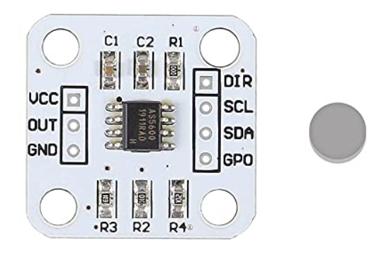
- 1x 6mm*2mm magnet (must be radially magnetized), normally comes with the AS5600 board set.
- 1x 61804-2RS deep groove ball bearing (20x32x7mm), normally < 5US$;
- 1x WS2812B LED ring board, use ones with dense LED arrangement (>=32 LEDs);
- 3x M4*10mm screws (large flat head is better) and hex nuts, for bearing.
- 4x M3*12mm screws, for spinning disc.
- 2x 1N4148 diode (choose ones easy to solder)
- 1x Custom cut acrylic disc, 4mm thickness.
- 11x 12mm non slip self-adhesive silicon pads (also for Keyboard).
https://www.amazon.com/Cabinet-Dampening-Adhesive-Circular-Stoppers/dp/B07XXWG818
Keyboard Materials
- 1x Raspberry Pi Pico.
https://www.raspberrypi.com/products/raspberry-pi-pico - 11x Kailh Choc v1 or v2 key switches, to get better play feel, 7 of them should be 50g linear.
https://www.kailhswitch.com/mechanical-keyboard-switches/low-profile-key-switches/burnt-orange-switch.html
https://www.kailhswitch.com/mechanical-keyboard-switches/key-switches/kailh-low-profile-switch-choc-v2.html - 7x Kailh low-profile stabilizers.
https://chosfox.com/products/kailh-1350-choc-switch-6-25u-stabilizer-set - 2x Panasonic 6mm square tactile switch EVQP1K05M.
https://www3.panasonic.biz/ac/e/dl/catalog/index.jsp?series_cd=3473&part_no=EVQP1K05M - 1x USB Type-C socket (918-418K2023S40001 or KH-TYPE-C-16P)
- 11x WS2812B-3528 RGB LEDs or if you want more challenge: 28x WS2812B-1516.
- 2x SN74LV1T34DBVR (SOT-23-5) level shifter, optional, for better voltage tolerance.
- 1x 0603 5.1kohm resistors for USB.
- 2x 0603 10ohm resistor.
- 5x 0805 1uF capacitors.
- 4x Kailh low-profile keycaps.
- 4x M3*6mm screws and hex nuts to fix parts together.
Detachable Cable
- 1x HDMI cable (ultra slim, diameter < 4mm), at least 50cm in length, we'll cut the HDMI connectors off, so pick a cheap one.
- 2X Magnetic pogopin connector sets, male and female. PCB side should use ones with 90-degree pins, cable side use ones with straight pins.

Step 1 - Buy
- Keyboard PCB
Just go JLC and make the order. Make sure the board thickness is 1.2mm, it's very important! - Turntable PCB
It's an optional one. It makes the wiring and soldering inside the turntable a litter easier. - Acrylic disc
Choose the dxf file according to your disc size and find a vendor to cut the 4mm black acrylic.
Documentation still in progress, come later...
Step 2 - 3D Print
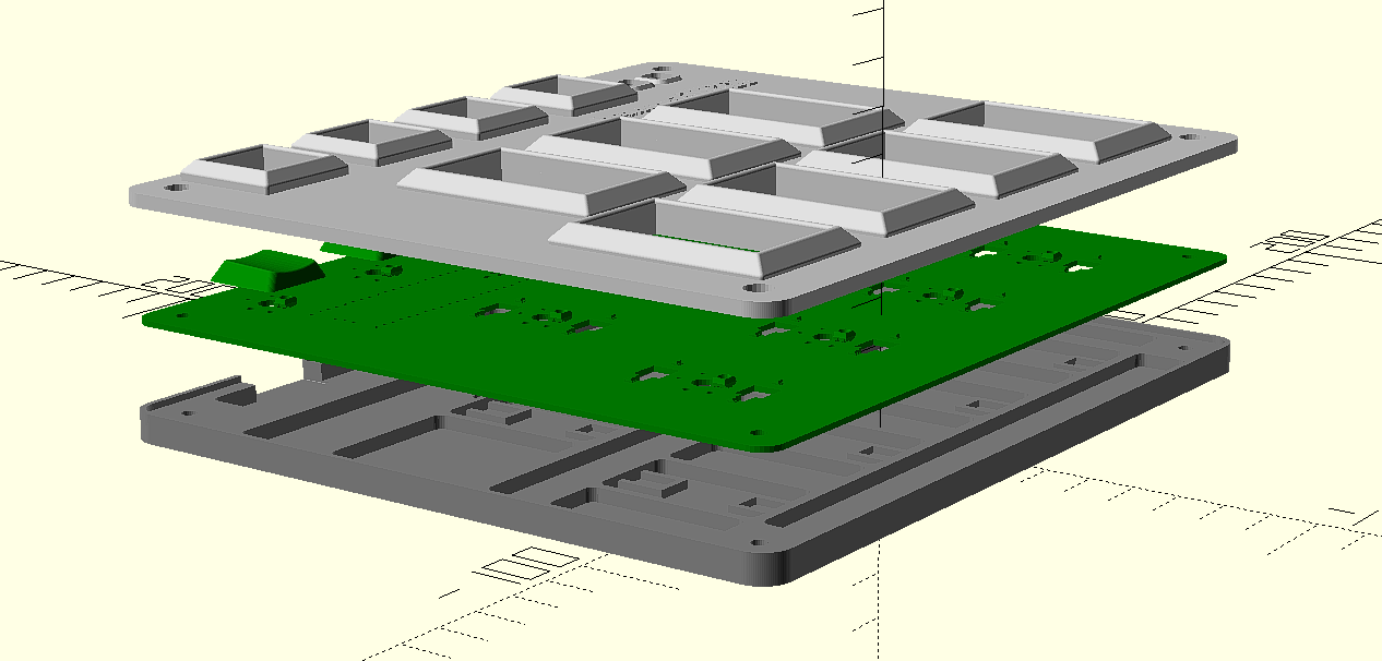
Keyboard
- PCB bottom (pcb_bottom_*.stl, choose one according to your connector choice)
FDM, PLA/PETG transparent, 0.2mm layer, 4 walls. - PCB top (pcb_top.stl)
FDM, PLA transparent, 0.2mm layer, 4 walls.
If you have Bambu Lab's AMS system, use PLA black/gray for 3.0mm+ layers.
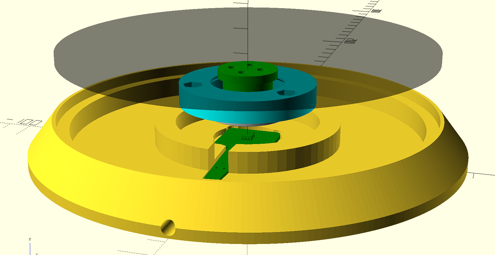
Turntable
For following prints, FDM, PLA, 0.4 nozzle, 0.16-0.2mm layer, 4 walls. And very important: "Seam Position" should be set to "Random" in your slicer.
These are all printed with
- Base (TT_base_xxx.stl), choose one of the 150, 170 or 180, based on your choice of disc size, 20-60% fill.
- Bearing seat (bearing_seat_6804.stl), 20-60% fill.
- Flange for disc (TTshaft_6804.stl), 60% fill.
Pogopin Connector
It's very small and requires higher accuracy.
- Housing for pogopin connector (pogo_bottom.stl, pogo_top.stl).
FDM, PLA, 0.2 nozzle is recommended, 0.1mm layer, 4 walls, 60% fill.
Button keycaps
SLA (resin), regular white, 0.05mm layer.
Step 3 - Solder
-
Turntable
There're a set of I2C and a WS2812B signal line together in the cable that connects turntable and the keyboard. Unfortunately, these signals crosstalk. So, we have to use shield cables for them. Two I2C lines should have a shield cable, and the WS2812B signal should have another shield cable. Good thing is, an HDMI cable has 4 shield cables and bunch of other small cables. We can make use of it.To ease the pain of soldering cables and 2 1N4148 diodes. I made a turntable PCB. But I haven't tried it myself.
Documentation still in progress, come later...
Step 4 - Assemble
- Assemble the turntable
- Install the low-profile stabilizers.
https://docs.keeb.io/choc-stabs
A little trick here is to leave the key switch unsoldered, after the stabilizer, the key switch and the keycap are in place, push the keycap down and then solder the key switch. This way the key switch can align to the stabilizers better. - Assemble the keyboard
Step 4 - Firmware
- For the new build, hold the BOOTSEL button while connect the USB to a PC, there will be a disk named "RPI-RP2" showed up. Drag the uf2 firmware binary file into it. That's it. There's a small hole at the back side of the keyboard, it is facing right to the BOOTSEL button.
- If it is already running my IIDX firmware, hold two small AUX buttons together will do the same as the BOOTSEL button.
- For now, some configurations are hardcoded, if you want to change something, you need to build by yourself.
Documentation still in progress, come later...
What If?
- I can't find pogopin connector.
I figured out another connector choice, which is a 3.5mm 4P headphone jack. It uses analog to communicate turntable movements, but I'm still testing it, so stay tuned. I will update this document. - I don't have Bambu Lab's machine, or I don't have an AMS system.
There're many online vendors and people providing paid Bambu printing service. Or you can just use other 3D printers. It's just the numbers in the OpenSCAD source file or STL files are finetuned on my Bambu Lab X1. You may need to adjust a little on your 3D printer system to get perfect result. And regarding the multi-color thing, maybe you can just paint the top layer by hand. I know people do miniature painting, I think it would be similar. - STL files are not accurate, difficult to assemble.
Solution: 3D printer systems are different one from another, it results in small differences even with same model file and some configuration. If the printed parts are not happy with each other, you can fiddle with the OpenSCAD source file and the numbers in it for your case. - I don't have resin printer.
- I can't find Kailh low-profile stabilizer.
- I don't have electronic DIY gears.
OK, this project is a electronic hobby project, maybe it's not for you if you don't plan to do electronic DIYs. You can buy good mini-cons online.
Documentation still in progress, come later...