7.8 KiB
(中文教程重写还在进行中)
软件配置
Windows 10
Windows 7 用户请注意,在win7平台一旦为Arduino上传过代码,不经过特殊操作便无法再次上传代码,如无必要请尽量使用Window 10操作系统。原因与解决办法如下:因为上传一次代码后,Arduino便会按照预定的那样伪装成NS控制器(设备名显示为POKKEN CONTROLLER),而win7无法识别这个硬件变动,没法自动给这个新硬件匹配上Arduino的驱动。如果实在避免不了使用win7,请手动修改Arduino驱动文件中的arduino.inf文件,将上传过一次代码的Arduino在设备属性中查到的设备ID写入到inf文件的列表里,并为被识别为POKKEN CONTROLLER的Arduino重新安装驱动。在本项目setup文件夹里有一份arduino-sample.inf文件,可以作为修改的参考,但是这份文件不保证能够直接使用,请自己负责修改。
Arduino IDE
在Arduino官网下载Arduino IDE这款软件,用来上传代码到Arduino板:https://www.arduino.cc/en/Main/Software?setlang=cn
软件魔改与Nintendo Switch相关
如果想要启动对Nintendo Switch的控制支持,你需要对Arduino IDE进行魔改,魔改后的Arduino不影响正常功能的使用。在setup文件夹找到HID.h和HID.cpp文件,替换掉如下位置的两个文件:
<Arduino IDE安装文件夹>/hardware/arduino/avr/libraries/HID/src/HID.h<Arduino IDE安装文件夹>/hardware/arduino/avr/libraries/HID/src/HID.cpp
之后将boards.txt的文件内容复制并粘贴到这个文件的末尾:
<Arduino IDE安装文件夹>/hardware/arduino/avr/boards.txt
上面的步骤完成后,下次启动Arduino IDE的时候应当可以在开发板中找到“Nintendo Switch Controller”这个选项:
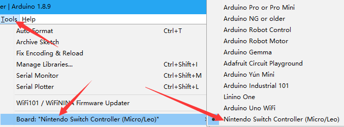
如果需要启动Nintendo Switch相关功能,请务必将此项选为开发板,并且注意选择合适的上传端口(上传之后端口可能会变化)。
切换键盘和NS手柄输出
想要开启或者关闭键盘或NS手柄输出,请按照下面的内容相应修改taiko_controller.ino开头附近的两行代码:
- 仅启用NS手柄输出
//#define ENABLE_KEYBOARD
#define ENABLE_NS_JOYSTICK
- 仅启用键盘输出
#define ENABLE_KEYBOARD
//#define ENABLE_NS_JOYSTICK
- 两者同时使用(未进行测试)
#define ENABLE_KEYBOARD
#define ENABLE_NS_JOYSTICK
Circuit Setup
Materials
To setup the circuit, you need an Arduino Leonardo, a set of four piezo sensors, and four 1MΩ resistors for some special cases.
Connect the Circuit
Connect the sensors to the 3.3v pin and the analog pins according to the diagram below:
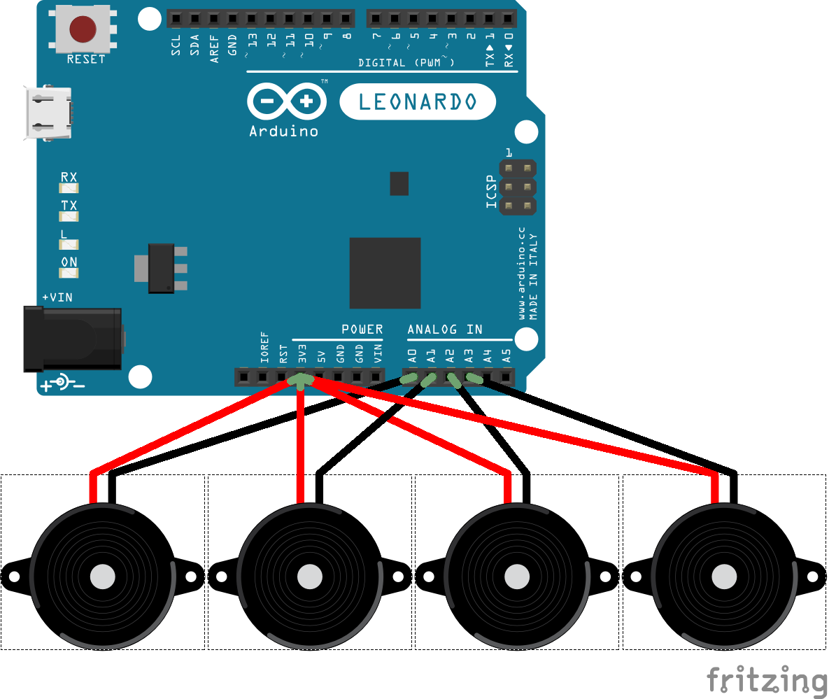
The mapping of the sensors by default should be:
- Left Rim: A0
- Left Surface: A3
- Right Surface: A1
- Right Rim: A2
To customize the mapping, checkout the parameter section.
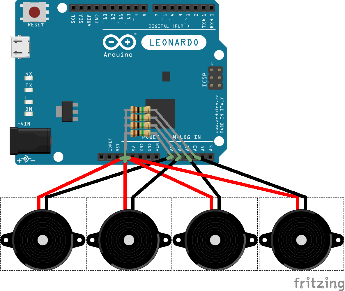
For most of the times, pluging the sensors directly into Arduino's pins will work. If the controller seems to be generating random inputs, you can fix this by plugging some 1MΩ resistors in parallel:
Notes
For best performance, the sensors must be piezo sensors (a.k.a. piezo speakers, contact microphones). No guarantee if other types of sensors will simply work, but if analog signals with voltage ranged 0-5V are fed into analog pins, this setup should be good to go.
For further improvements, you can use some diodes to limit the voltage of the piezo sensors, or use a 2.5v power supply, but this won't matter in most cases, at least on my side.
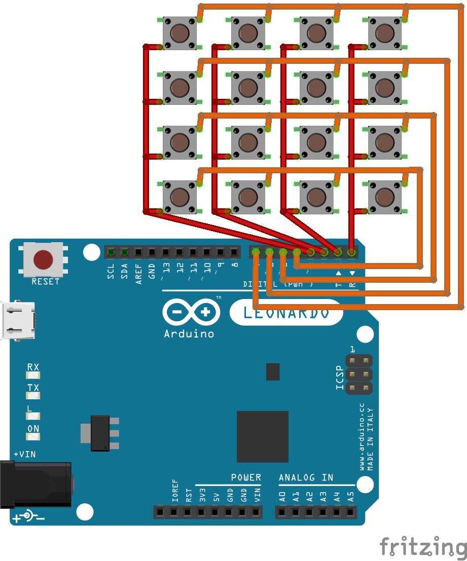
If you can somehow connect a 4x4 matrix keyboard (no pull-up resistors needed) to Arduino's digital pin 0-15, it will work as a controller along with the drum:
Algorithm
This sketch uses a dynamic threshold of sensor levels to trigger inputs. Whenever the sensor level from one sensor is higher than the threshold, a keyboard or Nintendo Switch controller input is generated, then the sensors will be put into a cooldown period. When an input is triggered or during cooldown period, the threshold will be raised to a ratio of current sensor levels, and after that the threshold will gradually decay by ratio, to hopefully be an envolope of the waves of sensor levels.
As the sensors should have biased input voltages, the sensor levels are actually the differential value of the analog value from analogRead.
To deal with four analog inputs, we read the sensor levels one at a time, and only do the triggering mechanisms for this sensor. To compensate the time difference, the sensor level for the current one will be a mix of values from previous read and current read. Also, a non-default non-blocking version of analogRead is used to guarantee more stablization time after a channel switch of arduino's internal ADC chip.
To deal with Nintendo Switch, I used the HID descriptor for Hori's Pokken fightstick to let Switch trust Arduino as a valid controller device (see the credits section). The default buttons from the four sensors are the analog stick buttons (press the sticks down) and the trigger buttons (ZL and ZR).
As VID and PID of the controller have to be the specific value, the setup to boards.txt is essential. Also, Switch seems also to be judging the device strictly by the first-come HID descriptor of the device, so Arduino's default HID behavior have to be altered to have our customized HID descriptor to work.
Parameters (with suggested values)
min_threshold = 15
The minimum value for sensor levels to trigger inputs for all sensors.
To determine an optimal value for this level, try enabling debug info. Usually, this value is only used to ignore sensor noises, but you can use this level as a sensitivity level.
cd_length = 10000
The cooldown length of sensors, in microseconds (=1x10^-6s).
While a sensor is in its cooldown period, no input will be triggered ignoring the sensor level. The threshold level would still be updated if the sensor levels go high. During the cooldown period, the corresponding key of the sensor is kept pressed. When it ended, the key is released.
k_threshold = 1.5
How much the threshold value is raised to, in ratio to the sensor level.
k_decay = 0.97
How fast every threshold level decays, in ratio per refresh (about 300ms).
For every refresh, the threshold value is multiplied by k_decay.
pin[4] = {A0, A3, A1, A2}
The analog input pins of four sensors.
key[4] = {'d', 'f', 'j', 'k'}
The key mapping of four sensors, if keyboard inputs are enabled.
sens[4] = {1.0, 1.0, 1.0, 1.0};
Sensitivity of every sensor. All sensor levels are scaled by these values respectively before use.
Debug Info
If the line #define DEBUG_OUTPUT is enabled, there will be debug info printed via serial. Take a look at your serial monitor.
The first 4 columns indicate current vibration level of the four sensors, and the last column indicates the threshold level for a sensor to trigger a input; the symbols in the middle shows current status of the sensors, # for input triggered and * for cooldown state.
A typical output could be:
0  3  13 63 |         | 0
51 2  11 58 | * * * # | 53
83 5  9  24 | # * * # | 83
Credits
- This sketch make use of Arduino IDE and its useful library. A modified version of the Arduino library is used to allow us to make a valid Nintendo Switch controller.
- The HID descriptor are a reverse engineering of Pokken Tournament Pro Pad of progmem's work: progmem/Switch-Fightstick
- The HID descriptor are coded using many useful macros and functions from LUFA Library