| jubeat Base wirelog cut.stl | ||
| Jubeat button.dwg | ||
| Jubeat button.pdf | ||
| Jubeat button.PNG | ||
| Jubeat Core 9587coreframe_v03_fixed_lower 114 .stl | ||
| Jubeat Core 9587coreframe_v03_fixed.stl | ||
| jubeat Front frame v4 CUT.stl | ||
| jubeat Front framev4.stl | ||
| jubeatIO Pro Micro.ino | ||
| README.md | ||
Jubeat-3D-printed-cab-edition-
A 300 x 300 Jubeat con
Hi
This is gonna be a quick and summarized version and im typing this while sleep deprived so feel free to ask me questions at
Discord : MiMi#4182

Things you'll need
-a printer with 300x300 printbed
-x64 microswitches(Like DM1-01P-30-3)
-arduino pro micro
-x50 M3x8x6
-x128 M2x10x4
-24"/23" monitor.
-and soldering set with thin wires (maybe awg20 wires)
-Intro
This was a project made to make Jubeat cons more accessible, I love the game a lot and I want to share my love for it by helping others achieve their cab goals. The project was mostly copied from a different project using mainly acrylic cuts and hardware, but made cheaper by using 3D printing and lesser hardware in total while only needing acrylic buttons.
This project is based on this other project made from acrylic but with no hex pins and only needing M2x10x4(x128 FRICTION FITTED INTO THE CORE FRAME) and M3x8x6(x50 on the front and base parts)
-3D PRINTED PARTS
there are 3 printed parts needed(no support needed)
Front("jubeat Front frame v4 CUT.stl" 1 wall),
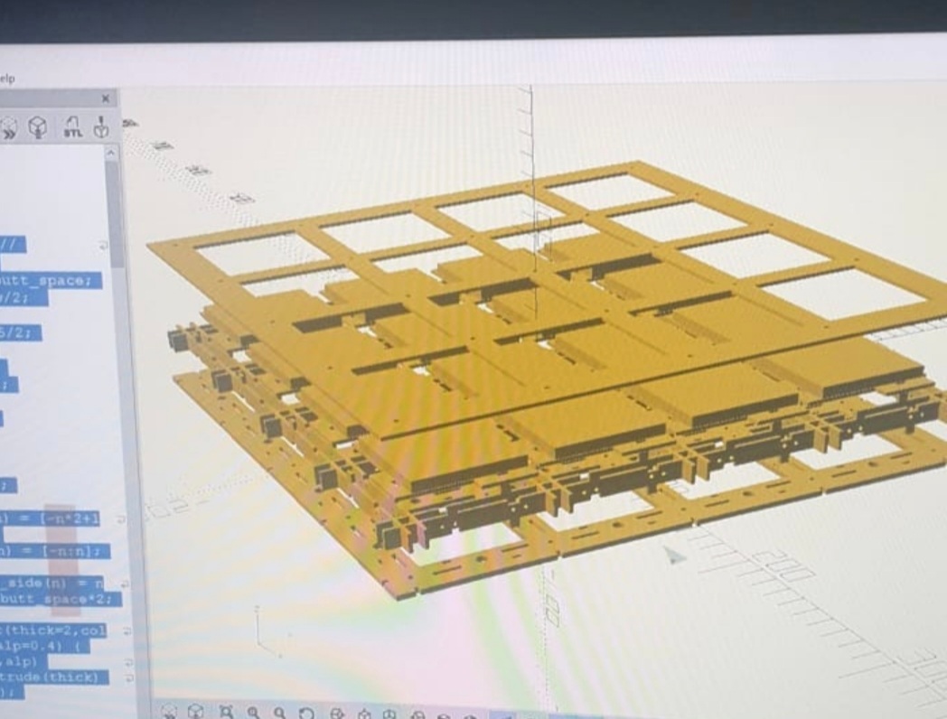
Core("Jubeat Core 9587coreframe_v03_fixed.stl" 3 walls 20% infill) &
Base("jubeat Base wirelog cut.stl" 1 wall).)
So the parts are sandwich into the following order top down Front, Core and then Base. The Core holds all the switches and each button will need a switch. these switches are the ones used for most mouses(Use the ones with the 2m mounting holes only and you'll need 64 of them)
-BODY
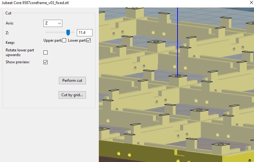
Jubeat Core 9587coreframe_v03_fixed.stl requires modification(cut along the Z axis to reduce height of the Core) for the switches you use based on the switches(Leaver or none) cuz travel distance of the switches differ a lot. The travel distance of each button would also require some changes to buttons(more on that in the button section). Make sure you test print the core first, insert a set of switches and a button and test the travel if you are particular about distance. If not cut the core about this much using Slic3r, This travel length should be perfect for almost any configuration.
-CODE AND BOARD
This project runs on "Arduino Pro Micro". codes are for that board at least. The code takes Inputs from all input points so just connect the buttons there and bind accordingly. I've got permission to host a copy of CrazyRedMachine's JubeatIO code and took the liberty to change the input points to suit the Pro Micro better. Upload "jubeatIO Pro Micro.ino" into your Pro Micro before you start assembly. Please do check out JubeatIO's Code for any updates etc. https://github.com/CrazyRedMachine/jubeatIO
-BUTTONS & SWITCHES
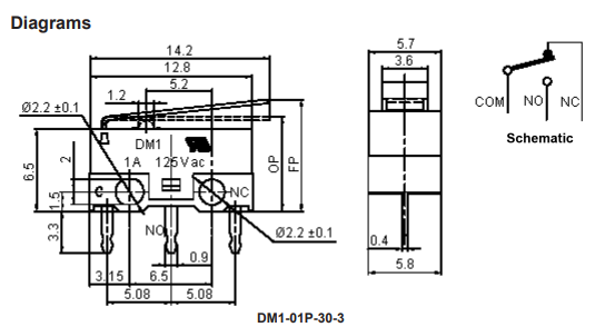
There a are many switches out there, Make sure the ones you are planning to use have a M2 size holes. I used DM1-01P-30-3 and some Huaon mouse switches for my leaver and non-leaver builds. Depending on your preference of switches, you'll have to adjust these parts(CORE and TOP PART of the button)
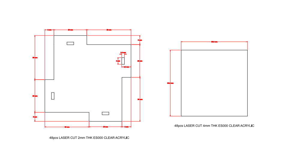
Buttons are laser cutted so refer to the picture for more information. There is also a laser cut file. The construction of the buttons contain 5.85cm square x 4mm acrylic (clear colorless) which makes up for the TOP PART. you'll have to glue it to the PDF stated "Jubeat button" x 2mm acrylic (clear colorless) which activates the switches. BOTTOM PART. I HIGHLY RECOMMEND FUSING WITH GLASS GLUE(THE ONES THEY USE FOR TV SCREENS) OR RESIN GLUE.Anything that cures with UV would be good. You can change the height of each button by stacking acrylic 5.85cm square x Xmm OR ordering a thicker square. This can help with the travel distance compensation. Gaps will be present between the frame and the buttons if your button travel distance is long. Make sure you get a thickness of 6mm for your TOP PART acrylic Square.
-ASSEMBLY
STEP 1
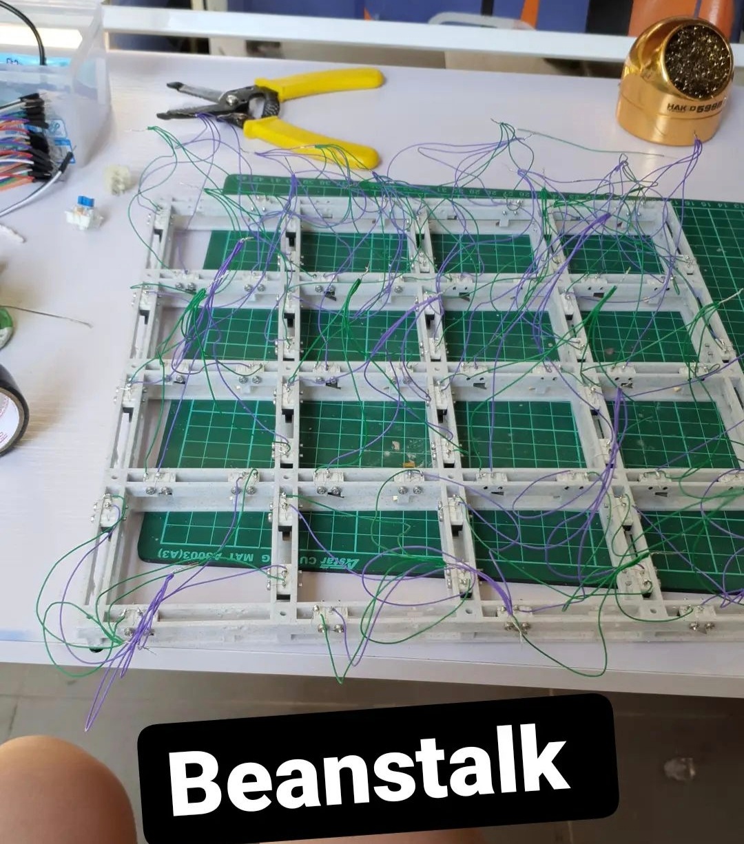
Insert all 64 switches into the "Core" first using th 2M screws. You will be using the core to hold all the switches in place for easier soldering. DONT HEAT UP THE SWITCHES FOR TOO LONG, IT'S EASY TO MELT THE SWITCHES AND DAMAGE THEM, WIRE WRAP THE SWITCHES IF POSSIBLE.
STEP 2
Solder and arrange 4 switches to one button based on the button's shape(refer to pic below) to the switches.(Each button needs 4 switches) Connect the 4 switches to one Main Wire out, and that wire would be the input for that button.
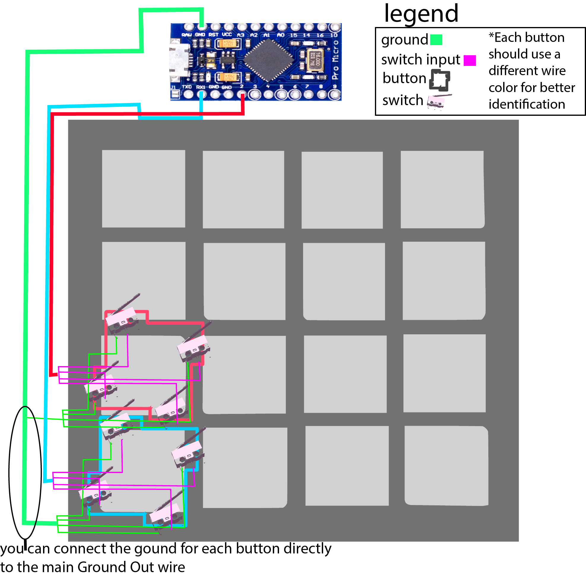 Repeat this 15 more times to and connect each button's Main Wire to the board.
STEP 3
Manage the wires and align them directly under the frame, you're gonna have to finesse the wires and tape them to the frame so they stay under the frame.
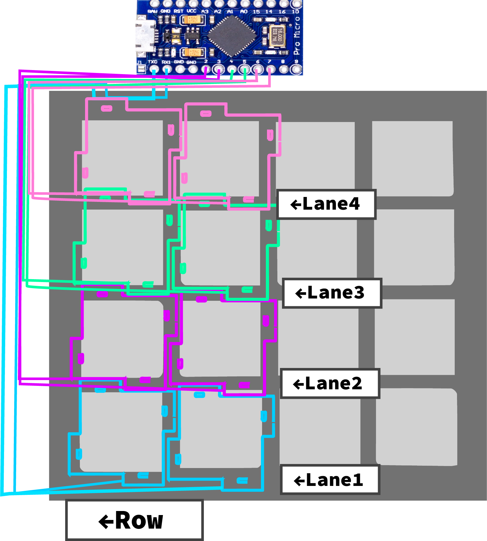
Feed the Main Wires out by rows and arrange them by "LANE", having two buttons in a Lane fead out to the direction they are closest too.
STEP 4
Once the wires are neatly arranged, Attach the "jubeat Base wirelog cut .stl" Part to secure the wires under the frame. Use x25(M3x8x6) for mounting.
STEP 5
Construct the buttons. Sand down the edges of the TOP PART acrylic button and create a smooth edge for charts with "sliding" involved(DO THIS ONLY ON ONE SIDE). Glue the TOP PART acrylic to BOTTOM PART acrylic button parts with the recommended glue, make sure to remove the acrylic protective film on the contact point where the buttons touch. Once the glue dries you can place them onto the "Core" assembly.
STEP 6
UPLOADING CODE AND TESTING. Upload joypad.ino to the Pro micro board. Run "set up USB Game Controller" program(pic below) and check if Arduino Leonardo is present, Click on Properties and press every individual buttons. Check if all buttons are working and Active.

STEP 7
MOUNTING. Once your controller is working, attach "jubeat Front frame v4 CUT .stl" with all 16 buttons in-between. If your buttons are getting stuck between the Front Frame, try using "jubeat Front thinned with logos .stl". Mounting onto a monitor is simple, you can use foam double sided tape to directly mount onto a screen. There are a lot of ways to mount, different monitors require different methods, you might need to figure out how to do this yourself.
STEP 8
Service> I/O INPUT CHECK> SCREEN CHECK> GAME SETTINGS> SCREEN TYPE A/B/AUTO> -ALSO- You should be left with 2 more extra input spaces on the arduino pro micro so feelfree to add some keyboard switches.
feel free to contact me about this project, I personally enjoy the game a lot and would like you to build this as well Thanks for reading ^^
Old videos from the other project.
Summary of the construction: https://youtu.be/bemd8mn8H4E