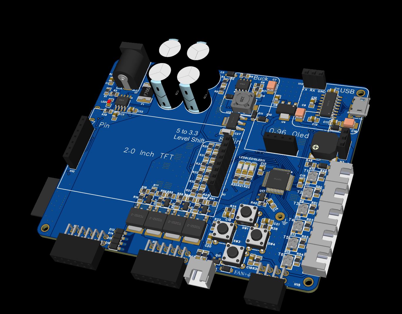
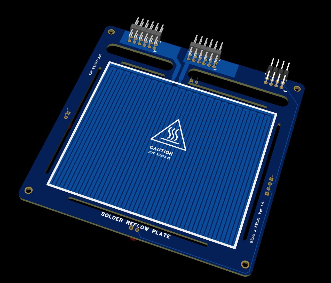
Solder Plate Controller with Detachable Hotplate
This repository contains the source code and design files for a Solder Plate Controller and detachable hotplate. Processor used is ATmega4809 and is based on the work of DerSpatz: https://github.com/DerSpatz/PCB-reflow-solder-heat-plate
Features
- Precise temperature control for soldering SMD components. with support of up to 6 thermistors.
- Cheap and widely available MCU- Atmega4809 and low BOM cost
- Custom PCB design with 2 version: Single area control (Completed) and 4 independent heating zones control(In works)
- Detacbale hotplate allows for use of new heatplate designs including larger ones
- Programming via USB
- PlatformIO integration for streamlined development.
- wifi via esp8266-12f module (with wifi version - In Development).
- Based on Reflow Hotplate by DerSpatz with some improvements
- Oled for menu navigation, debbuging and thermistor info
- TFT for reflow profile target and actual temp
- 4 buttons for menu nativation
- Current sense IC for current monitoring
- 3 indicator LED's. They work for both menu and REFLOW profiles (Blinking while on the current stage and solid once profile stage is complete)
- Buzzer for complete notification
- Buck- Converter for input voltage allowing up to 24V in
- 24V+ rated input voltage stage components allowing theoretcally up to 24V to be used (not yet tested)
- Optional fan for cooling stage (Not yet implimted)
- Included files for a case and guard for the detachable plate terminal guard
Getting Started
Prerequisites
- PlatformIO Core or PlatformIO IDE.
- ATmega4809 microcontroller and all the BOM components
- Basic soldering tools and electronic assembly skills.
- Access to a PCB manufacturing service or soldering equipment (solder paste, hot air gun, tweezers)
- Some basic technical skills
Hardware Setup
- PCB Fabrication: Fabricate the PCB using the provided gerber files. You can use these to order the naked PCB from services like JLCPCB
- Component Assembly: Solder the components onto the PCB as per the schematic or choose a SMT assembly service like the ones from JLCPCB
- Power Supply Connection: Choose a suitable power supply. 12V 5A tested, 24v 5A compatible. Use of more then 5A requires a appropriate FUSE to be chosen and solder on place of F1
Preparing the ATmega4809
Before programming the ATmega4809, it needs to be flashed with a default bootloader.
- Bootloader Flashing:
Same process as DerSpatz Solder plate (Direct quote):
The MCU can be programmed with JTAG2UPDI (https://github.com/ElTangas/jtag2updi). For programming, you need an Arduino with ATMEGA328p (Uno or Nano), some wires, a 4.7k resistor and a 10µF capacitor or 120 Ohm resistor to disable the auto-reset.
JCM from the Discord explained the process pretty good:
- Download/Clone this project: https://github.com/ElTangas/jtag2updi and rename the folder "source" to "jtag2updi" (otherwise the Arduino IDE won't like it)
- Open jtag2updi/jtag2updi.ino in your Arduino IDE
- Configure the flasher options for your Arduino Nano and flash it
- Connect D6 of your Arduino Nano over the 4.7kOhm resistor to the UPDI pin of the board and 5V to 5V and GND to 0V
- Add the MegaCoreX hardware package to the Ardunio IDE (see https://github.com/MCUdude/MegaCoreX#how-to-install)
- Install the Adafruit_GFX, Adafruit_SSD1306, DallasTemperature and Debounce2 libraries with the Library Manager (you might not need all of them depending on which firmware you plan to use)
- Download and open the ino you want to upload to the ATMEGA4809 (https://github.com/DerSpatz/PCB-reflow-solder-heat-plate/blob/main/Firmware/pcb_reflow_fw/pcb_reflow_fw.ino)
- Select the options for the programmer (Board: ATmega4809, Clock: Internal 16 MHz, BOD: 2.6V or 2.7V, EEPROM: retained, Pinout: 48 pin standard, Reset pin: Reset, Bootloader:Optiboot:Uart0(Defualt pins)) and select the port of your Ardunio Nano as Port
- Make sure the programmer selected is SerialUPDI or JTAG2UPDI
- Select Burn Bootloader and see if it runs through
-
MicroUSB Programming And Firmware Upload:
- Using Platformio:
- After flashing the bootloader, the ATmega4809 can be programmed via the microUSB connection using PlatformIO by building the project and upload // Use a AVR programmer or the jtag2updi modified arduino nano/uno menitoned above
- Using AVRDude
- Folow instructions on : https://github.com/ElTangas/jtag2updi?tab=readme-ov-file#using-with-avrdude
- Example : avrdude -c jtag2updi -P com7 -p t1614
- Using AVRDUDESS (AVRDUDE with GUI interface) -- This section many not be completley finished
- Download and install AVRDUDE 6.3 :https://download-mirror.savannah.gnu.org/releases/avrdude/
- Download AVRDUDESS : https://github.com/ZakKemble/AVRDUDESS
- Download the custom Avrdude config: https://svn.savannah.gnu.org/viewvc/checkout/avrdude/trunk/avrdude/avrdude.conf.in?revision=1422
- Select the custom avrdude.conf from Option -> avrdude.conf - > choose where you downloaded the custom conf file
- Choose the programmer as jtag2updi
- Choose the COMPORT where the jtag2updi modified arduino is connected to
- Choose the Flash binary under the precomplied binary directory -> set to Write
- Press Go
Software Installation
-
Clone the Repository:
git clone https://github.com/arwidcool/Solder-Plate cd Solder-Plate -
Import in vscode To open a PlatformIO project in VSCode with the PlatformIO extension, follow these steps:
-
Launch VSCode and ensure that you have the PlatformIO extension installed. If not, you can install it from the VSCode marketplace.
-
Open the VSCode command palette by pressing Ctrl+Shift+P (Windows/Linux) or Cmd+Shift+P (Mac).
-
In the command palette, type "PlatformIO: Open" and select the "PlatformIO: Open" command from the list.
-
Navigate to the root folder of your PlatformIO project using the file explorer that appears.
-
Select the folder and click "Open" to open the PlatformIO project in VSCode.
Usage
Power On: Connect the controller with a 12V 5A(Tested working) or 24V 5A PSU (Untested) Set Profile: Navigate the menu and choose the desired reflow profile Start Soldering: Place your PCB and components on the hotplate and start the profile
Customization
Feel free to modify the firmware and PCB design to suit your specific needs.
Contributing
Contributions are welcome. Please follow standard procedures for contributing to open-source projects.