| ATmega32U4 | ||
| ESP32 | ||
| ESP32-S3 | ||
| ESP32-S3-Analog | ||
| images | ||
| .gitignore | ||
| LICENSE | ||
| README_ja-JP.md | ||
| README_zh-CN.md | ||
| README.md | ||
Taiko Drum Controller - Arduino (ATmega32U4/ESP32)
Open-source hardware program to make your own Taiko no Tatsujin PC controller. It can emulate as a keyboard, or as an analog joystick to enable hitting force sensing - just like how you play on the arcade machine. Now also support 2 drums so you can enjoy the game together with your friends at home!
About this Project
This project aims to help you develop your own hardware taiko at home.
This program is for personal and non-commercial use only.
What You Need
-
An Arduino Micro/Leonardo (ATmega32U4) board or an Arduino Nano ESP (ESP32) board.
Most ATmega32U4 boards work, but you need to verify that they support keyboard emulation; ATmega328P boards like Arduino Uno don't work.
ESP32 is strongly recommended because it's significantly more powerful than ATmega32U4. This project uses an ESP32-WROOM-32 board.
-
4 piezoelectric sensors.
-
8 100kΩ resistors.
-
(Optional) 4 bridge rectifier chips such as DB107 (see the Additional Notes section for details).
-
(Optional) Some red and blue LEDs.
-
Necessary electronic components (breadboards and jumper wires, etc.).
-
Wood planks and cutting tools (only if you need to make your physical taiko drum from scratch). If you have an aftermarket taiko or a Big Power Lv. 5 drum, you can use them directly.
Steps to Make the Controller
-
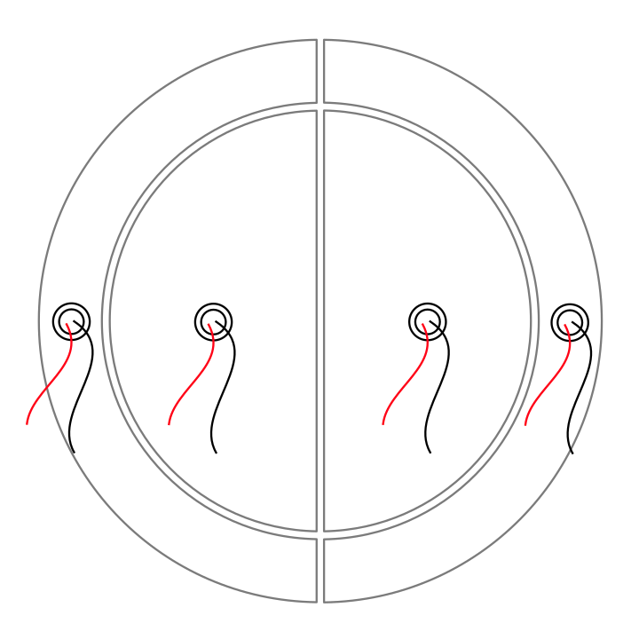
Make the drum and firmly glue the 4 piezoelectric sensors to the drum. Refer to the image for preferred locations of the sensors.
-
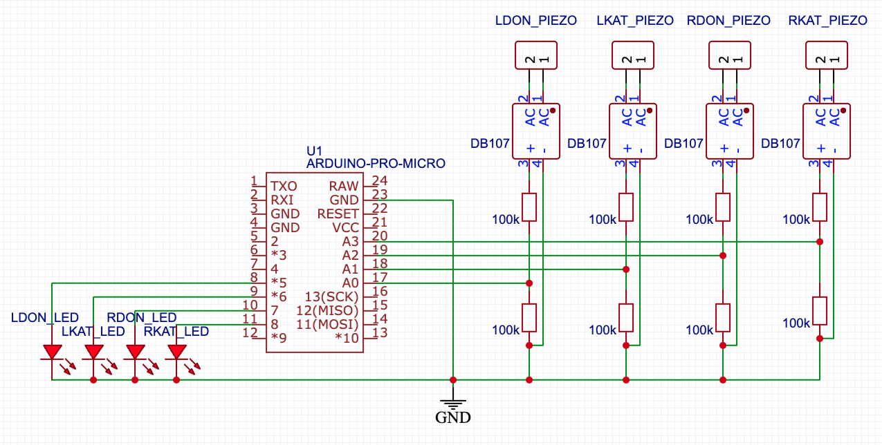
Connect the piezoelectric sensors and other components to the controller as follows (the polarity of the piezoelectric sensors don't matter);
The following schemes are for Arduino Micro boards. If you use a different board, refer to its documentations for the connection.
If you choose to add the bridge rectifiers, use the following scheme:
-
Flash the firmware to the board.
You may need to fine-tune some parameters like
SAMPLE_CACHE_LENGTH,HIT_THRES,RESET_THRES, andsensitivity. See the following section for details. -
Have fun!
Tuning the Parameters
-
Hit and reset threshold
Set
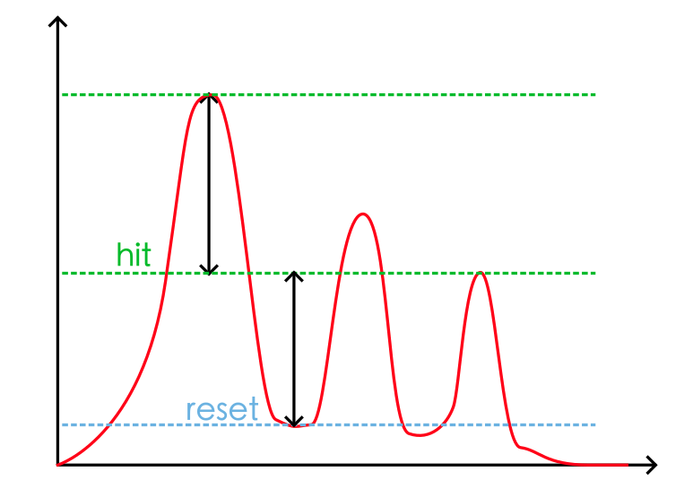
DEBUG 1(this disables the keyboard output and sends signal values from the serial port), flash the firmware, roll on one of the 4 areas of the drum, and visualize the graph from the output of the serial monitor. The hit threshold should be lower than your heaviest hit on the drum, and the reset threshold should be greater than the trough between roll hits. The reset value should also be below the hit value.Repeat the process for the rest 3 areas and find the best one that fits all.
-
Sampling length
For maximum runtime speed, the
cache.hlibrary has been optimized to work withSAMPLE_CACHE_LENGTHwindow sizes of powers of 2. That means 2, 8, 16, and 32, etc. Practically 16 is the best value for Arduino, but if you have a powerful microcontroller that samples the input at the speed of at least 4000Hz or more, you can change the value to 32 for a smoother (in other words, less noisy) curve. -
Sensitivities
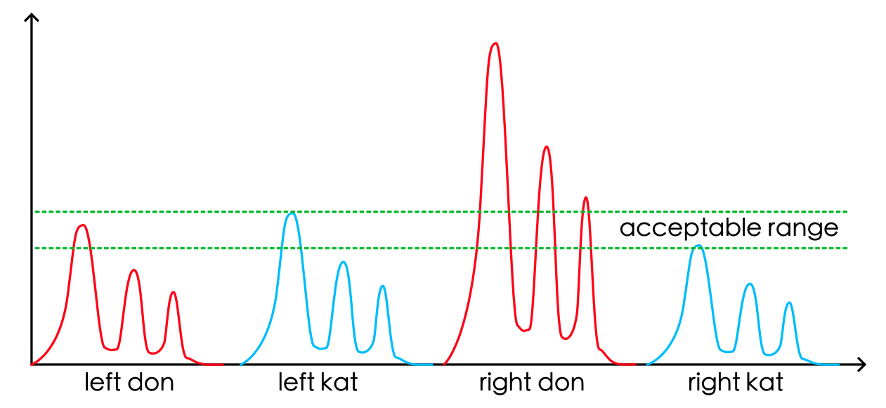
Not all piezoelectric sensors are the same, and due to installation errors, the captured signals from the 4 sensors may vary significantly. The sensitivity values are multipliers to normalize the differences. In the following example, the right-don area generates a much higher value than the rest 3, so you can adjust
sensitivityto{1.0, 1.0, 0.5, 1.0}to eliminate the issue.Note that the installation of the sensors is very critical. You should make sure that the sensors are firmly attached on the wood and located properly.
Additional Notes
-
Why using bridge rectifiers
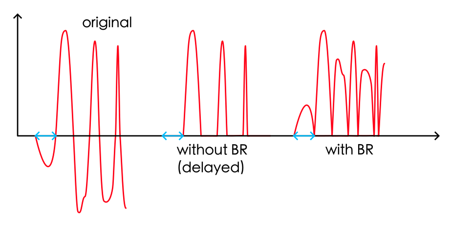
Without biasing the voltage of the piezoelectric sensors, their output voltage range is about -5V to +5V. However, the ADCs of the analog inputs only accepts positive voltage values (0-3.3V for ESP32 and 0-5V for ATmega32U4). When they receive a negative voltage, it's simply truncated to 0.
It's usually okay for normal electronic drums because we're just losing half of the input energy and it doesn't influence how we calculate the hitting time. But it can cause problems for taiko drums, especially with slow processors like ATmega32U4.
In a taiko drum, all the 4 vibrating pieces are connected together, meaning that if you hit left-don, the processor also receives signals from left-kat, right-don, and right-kat. If the left-don piezoelectric sensor generates a negative voltage at the beginning and is truncated by the ADC, it will cause a minor "delay" of about 3 to 4 milliseconds, and the processor could incorrectly treat this hit as a right-don, a left-kat, or even a right-kat, whichever sends a highest positive value.
Using a bridge rectifier, all negative values are converted to positive. In other words, it's like the
abs()function, ensuring that we don't lose any negative voltages.
Taiko Controller - Analog Input Mode (Beta)
With ESP32-S2 or ESP32-S3 controllers, instead of keyboard emulation, the drum controller can work as a gamepad and send its axes values to the game (which also must support analog input). In this way, the game can recognize different force levels of the hit.
If you prefer to use the Arduino Micro/Leonardo board, please refer to the Arduino XInput Library to implement the gamepad.
What You Need
-
Make your drum or use Taiko Force Lv.5.
-
Flash
ESP32-S3-Analog/ESP32-S3-Analog.inoto your controller. -
A working game, with these modifications:
-
Backup and replace the
bnusio.dllfile in the game folder with the one here in theextra/folder.This file is compiled from this fork and you can compile it by yourself if you want.
This modified library only works with a specific game version. If it breaks your game, please clone the original repository, make the corrensponding modifications, and compile it.
-
Open the
gamecontrollerdb.txtfile in the game folder and add one entry under#Windows:030052a8694800006948000000000000,Taiko Controller,-leftx:-a0,+leftx:+a0,-lefty:-a1,+lefty:+a1,-rightx:-a2,+rightx:+a2,-righty:-a3,+righty:+a3,platform:Windows,This will tell the game that our ESP32 controller is a gamepad called "Taiko Controller", and map the axis to the standard SDL2 library so that the game can recognize the analog inputs.
-
Open the
config.tomlfile and add the following lines at the end:
[controller]
analog = true
Note that with
analog = true, all the keyboard drum inputs are disabled. Sorry for this but it need further refactoring to make them work together. If you want to switch back to keyboard inputs, setanalog = false. -
-
Launch the game and enjoy!
Online Signal Visualizer Tool
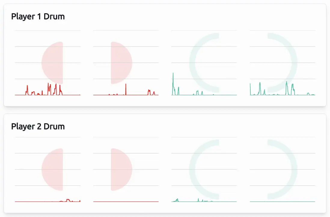
If you find debugging and finding the best sensitivity values very inconvenient with serial port's communications, you can use this taiko signal visualizer. It's a simple tool I created to show the output of the Taiko Controller (ESP32-Analog version only).
Just connect the board to the computer (using the USB port, not the serial port) and the waveform will be shown in the graphs. So you don't need to turn on debug mode or using Serial.print() command to obtain the values to tune the sensitivities.
How it works
The analog version of the controller simulates as a gamepad and sends the hit force values to the game as the axis values of the left and right joysticks. So with the built-in Gamepad API it's very easy to read the values directly. To prevent the tool reading from other gamepads, the controller must be named with Taiko Controller (Vendor: 4869 Product: 4869), so please don't change the pID and vID values in the firmware.
