13 KiB
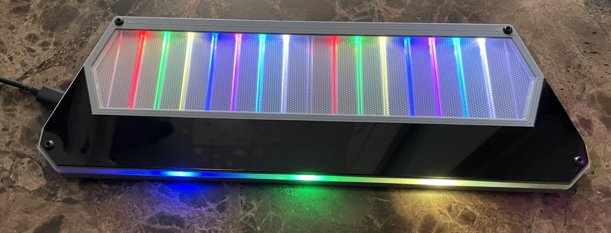
Chu Pico - Chunithm Style Mini Controller
Features:
- It's small, made for 15-17 inch screen.
- Air towers are replaced with built-in ToF sensors.
- Traditional IR Air mechanism is also provided for DIYers.
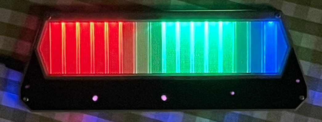
- HID lights, of course!
- 32 keys (upper and lower rows).
- Follows CrazyRedMachine's RedBoard I/O protocol.
- Command line of rich features.
- All source files open.
Thanks to many respectful guys/companies who made their tools or materials free or open source (KiCad, OnShape, InkScape, Raspberry things).
And thanks to community developers that inspired me and helped me: CrazyRedMachine (https://github.com/CrazyRedMachine), SpeedyPotato (https://github.com/speedypotato).
And also:
- RP_Silicon_KiCad: https://github.com/HeadBoffin/RP_Silicon_KiCad
- Type-C: https://github.com/ai03-2725/Type-C.pretty
Notes
This one is relatively easy to build compared with my other projects like IIDX Pico or Teeny. You can check out my other cool projects.


- Popn Pico: https://github.com/whowechina/popn_pico
- IIDX Pico: https://github.com/whowechina/iidx_pico
- IIDX Teeny: https://github.com/whowechina/iidx_teeny
- Chu Pico: https://github.com/whowechina/chu_pico
- Mai Pico: https://github.com/whowechina/mai_pico
- Diva Pico: https://github.com/whowechina/diva_pico
- AIC Pico: https://github.com/whowechina/aic_pico
- Groove Pico: https://github.com/whowechina/groove_pico
This Chu Pico project:
- Heavily depends on 3D printing, you need a Bambu 3D printer (X1 or P1).
- Requires skills to solder tiny components.
Disclaimer
I made this project in my personal time with no financial benefit or sponsorship. I will continue to improve the project. I have done my best to ensure that everything is accurate and functional, there's always a chance that mistakes may occur. I cannot be held responsible for any loss of your time or money that may result from using this open source project. Thank you for your understanding.
About the License
It's CC-NC. So DIY for yourself and for your friend, don't make money from it.
HOW TO BUILD
Frequently Made Mistakes
Many DIY enthusiasts commonly make certain mistakes during the building process. Please proceed with extra caution to avoid these.
- MISTAKE: Soldering everything together without conducting intermediate testing.
Remember, even professional engineers can make mistakes. It becomes significantly harder to identify the root cause of a problem when all components are already assembled or soldered. Therefore, it's advisable to solder and test in stages. The firmware is designed to function correctly even with some components missing, which is good for testing. - MISTAKE: Neglecting to cut the ADDR pin trace on the MPR121 module.
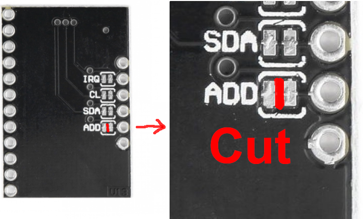
The MPR121 module in the market has the ADDR pin pre-connected to ground. But the board expects a floating ADDR pin, otherwise the ADDR pin will short the circuit. Please verify your "CUT" using a multimeter. - MISTAKE: Rushing to replace components when something fails.
Sometimes people prematurely assumes that the Raspberry Pi Pico or other modules are faulty. Be aware that desoldering and soldering large SMD components is a challenging task. It carries the risk of damaging the component or the PCB board. Patience and caution are crucial. Look at the schematics and PCB design files and ask help from community first. Questioning the integrity of these components should be your last resort. - MISTAKE: Failing to properly solder the 3 USB pins of the Raspberry Pi Pico.
These pins are at the bottom side of the PCB. It's a common oversight to either forget to solder them or to leave air bubbles during the process. To avoid this, solder slowly from one side of the hole, using minimal solder wire and a generous amount of flux.
PCB
-
Go JLCPCB and make order with the gerber zip file (latest
Production\PCB\chu_main_xxx.zip), regular FR-4 board, black color, thickness is 1.6mm. -
1x Rasberry Pico Pi Pico or Pico W.
https://www.raspberrypi.com/products/raspberry-pi-pico Becareful of 3 pins that are at the other side, they're difficult to solder and may leave air bubbles.
-
1x USB Type-C socket (918-418K2023S40001 or KH-TYPE-C-16P)
-
36x WS2812B-4020 side-facing RGB LEDs.
https://www.lcsc.com/product-detail/Light-Emitting-Diodes-LED_Worldsemi-WS2812B-4020_C965557.html -
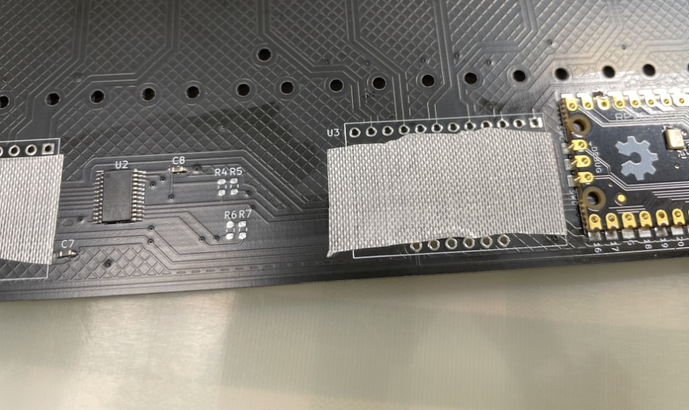
TCA9548APWR (TSSOP-24) I2C multiplexer.
https://www.lcsc.com/product-detail/Signal-Switches-Encoders-Decoders-Multiplexers_Texas-Instruments-TCA9548APWR_C130026.html -
3x MPR121 modules, there're many types in the market, choose ones like this.
https://www.sparkfun.com/products/retired/9695
Before solder MP121 module to the main PCB board, remember to use a knife to cut (unshort) the tiny trace that connects ADDR to the GND. Please be careful not to cut more than necessary.
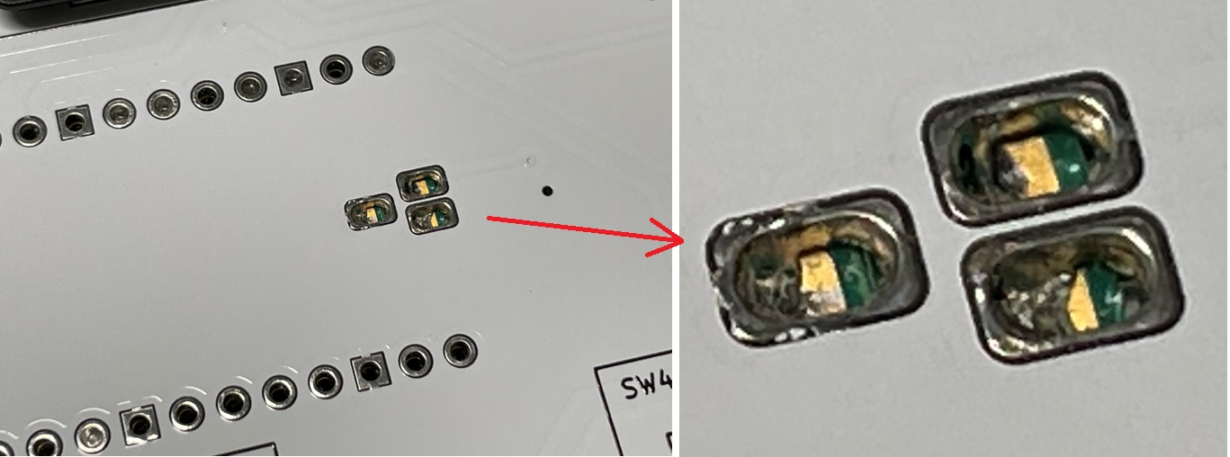
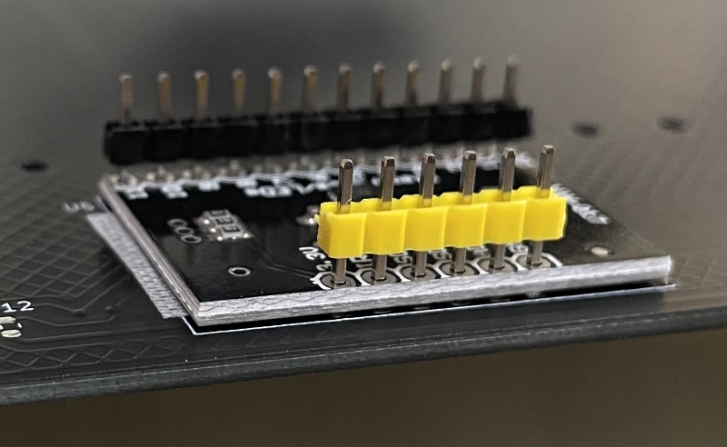
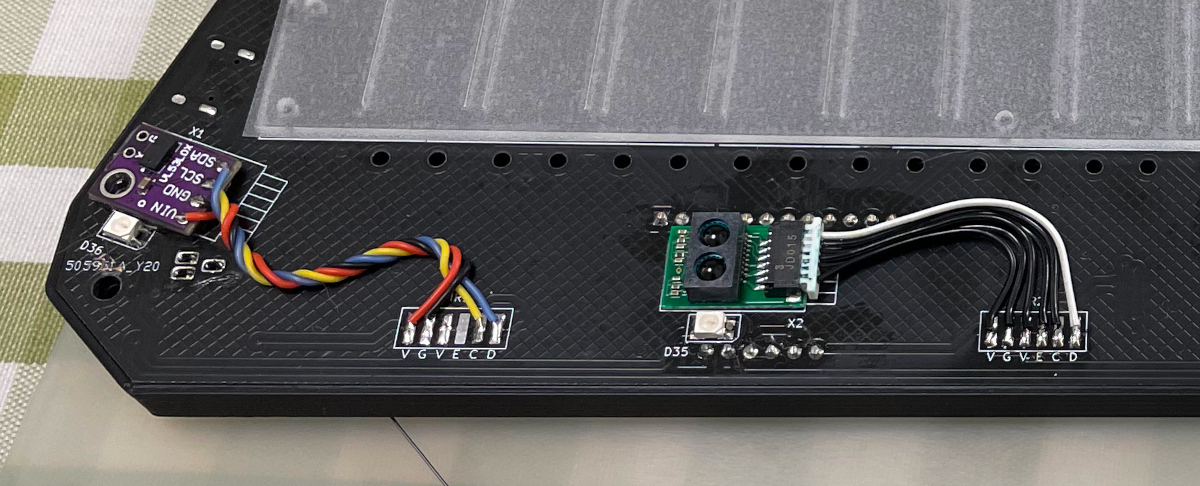
There's not enough space for the whole height of MPR121 module plus the lead pads. So you need to solder the module like the picture shows below.
First apply some insulation tape.
Then solder the module directly against the PCB.
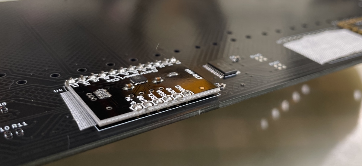
You can use the pins comes with the module, but you need to cut away the plastic pads.
-
5x Sharp GP2Y0E03 or ST VL53L0X ToF sensor modules, you need cables as well.
https://www.lcsc.com/product-detail/Angle-Linear-Position-Sensors_Sharp-Microelectronics-GP2Y0E03_C920270.html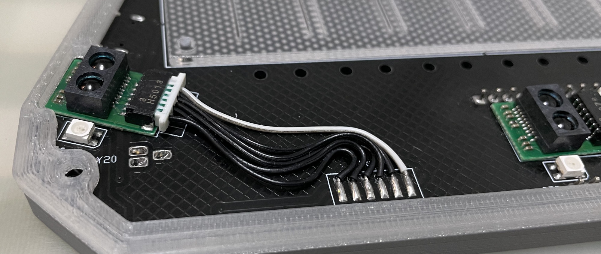
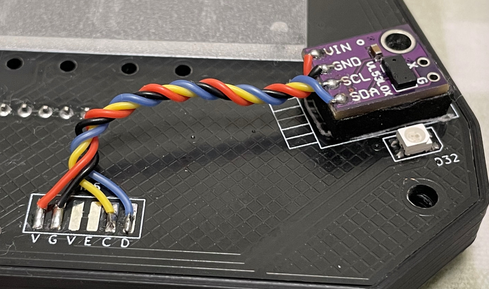
You can use both of them in a same PCB, the firmware will identify each of them automatically.
-
2x 0603 5.1kohm resistors (R1, R2) for USB.
-
1x SN74LV1T34DBVR (SOT-23-5) level shifter (U8), if you can't find one, use a 0603 10ohm resistor (R3) as an alternative.
https://www.lcsc.com/product-detail/Buffer-Driver-Transceiver_Texas-Instruments-SN74LV1T34DBVR_C100024.html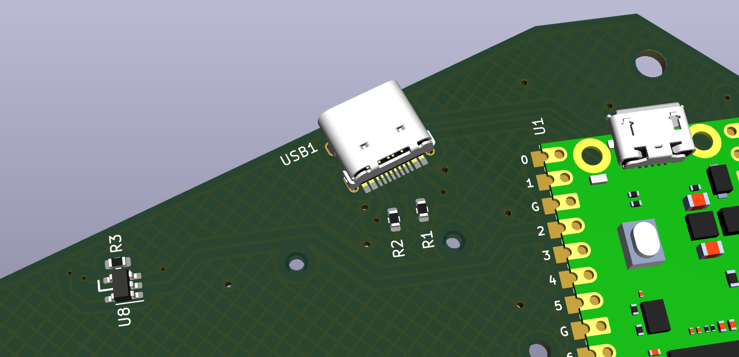
-
8x 0603 1uF (0.1~1uF all fine) capacitors (C1 to C8), OPTIONAL, recommended.
-
10x 0603 5.1kohm (1~5.1kohm all fine) resistors (R4 to R13) for I2C pull-up, required for overclock I2C.
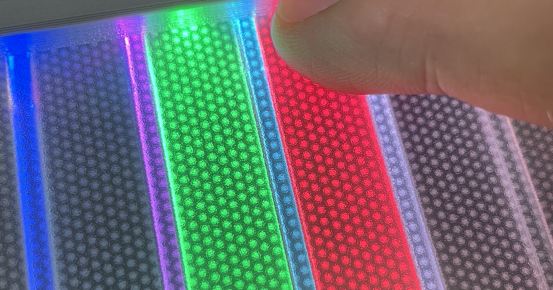
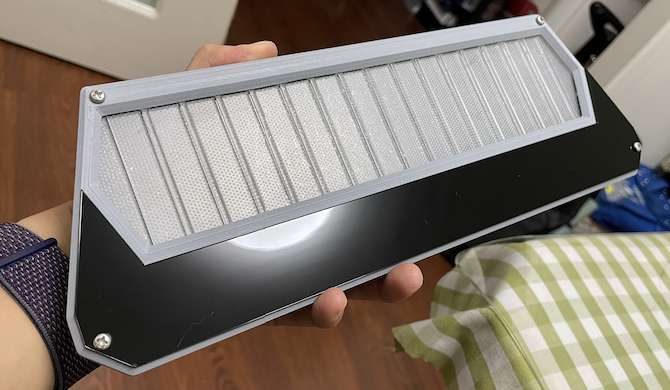
Light Guide Panel
- Find a service to cut a light guide panel using DXF or DWG file
Production\CAD\chu_pico_lgp.*, the size is 256mm*60mm, 1.8mm to 2.0mm thickness, thinner is better for sensitivity. 2.0mm is easy to find, 1.8mm is rare. I used 1.8mm for my build.

- LGP material choices:
- Real LGP (Light Guide Panel) material, it's the best choice.
- Clear Acrylic with Light Guide Film, it's a good choice.
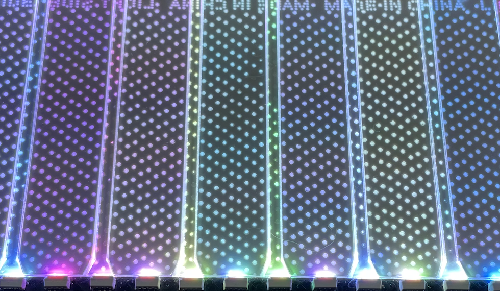
- Clear Acrylic with single-side-frosted, it's a good choice.
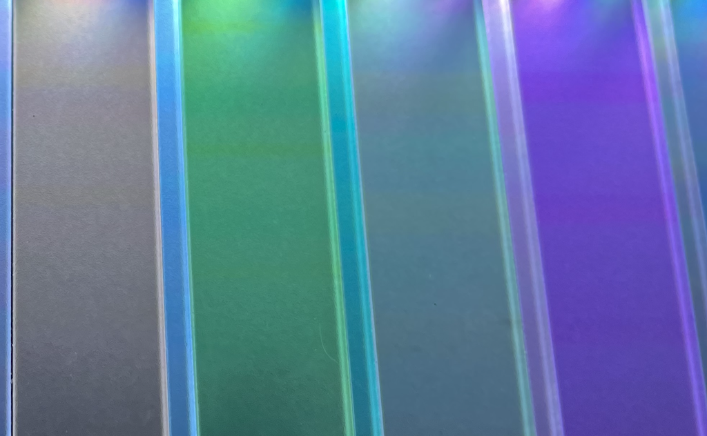
- Clear Acrylic with manual single-side-sanding, it can work too.
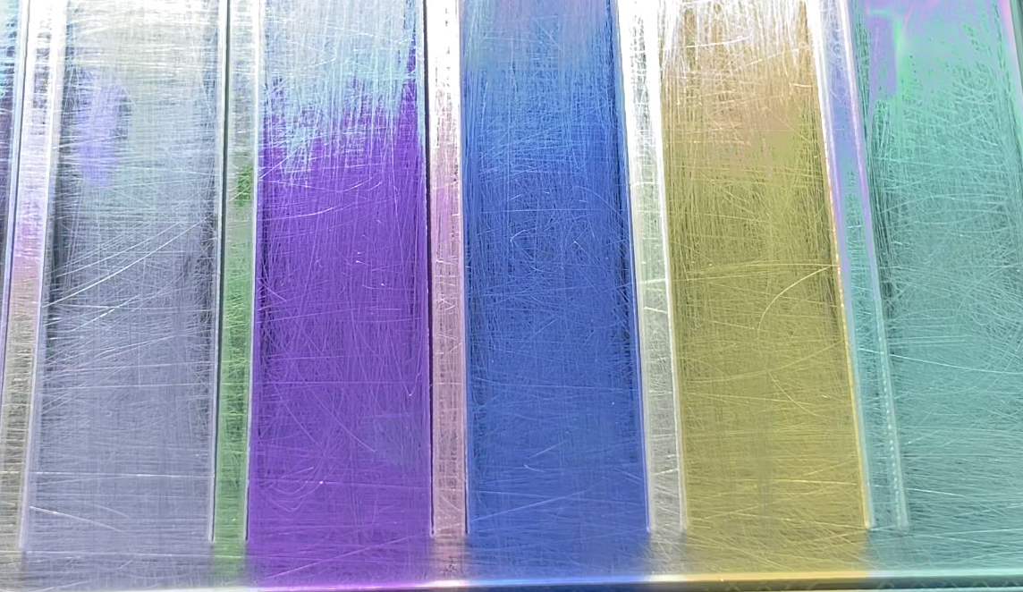
- Real LGP (Light Guide Panel) material, it's the best choice.
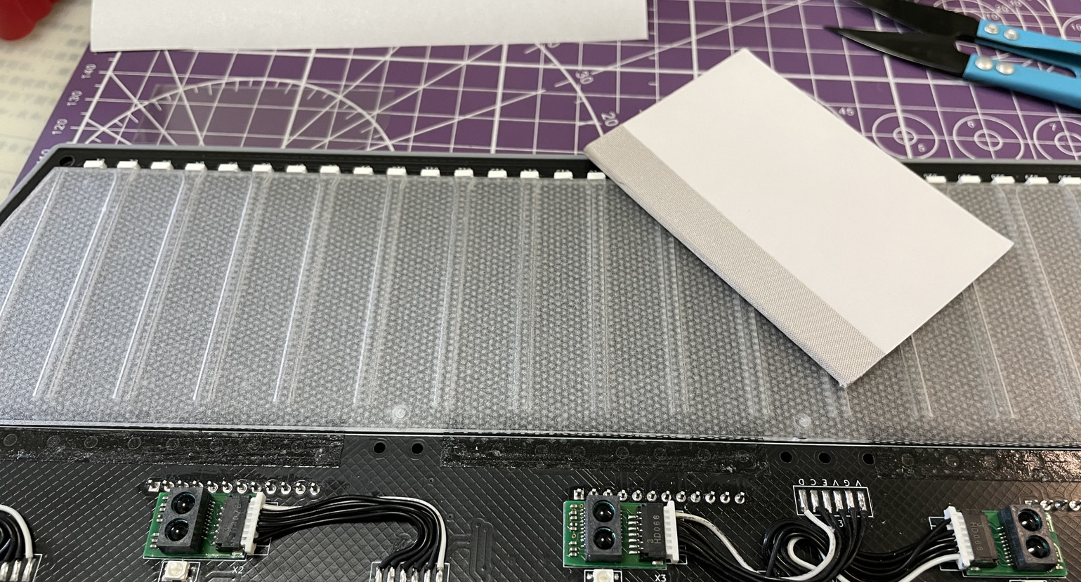
Panel Film
- A self-adhesive textured/frosted film sheet, it is applied on top surface of the light guide panel. It improves touch feel. You can use window sticker film. It MUST be self-adhesive ones, NOT static cling ones. They're usually very cheap.
- Cut the film to roughly match the shape of the light guide panel, and stick to the panel.
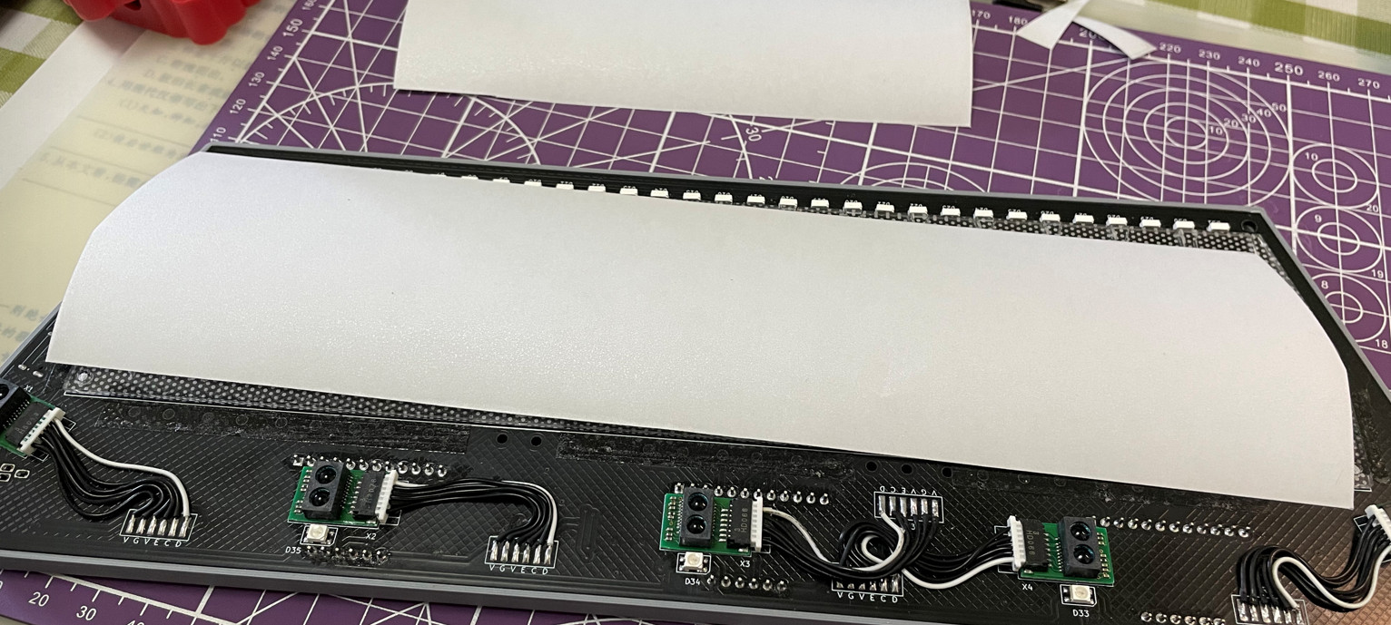
- Gentlely rub the film to remove any air bubbles and make it stick tightly.
IR Cover
- It's for good looking, as it hides 5 ToF sensors.
- IR lights can go through.
- Find a service to cut an IR cover using the DXF or DWG file
Production\CAD\chu_pico_ir_cover.*, the size is 293.2mm*63.5mm, 1mm thickness. The material must be "Infrared Transmitting Acrylic Sheet" which can block visible lights (so it looks black) while letting IR lights go through.
- If you can't find one, cut a regular smooth surface acrylic, but it can't hide the ToF sensors which are not good looking.
- If you're using the VL53L0x ToF sensor, please add padding beneath the sensor. This brings it closer to the acrylic cover, which can prevent acrosstalk error.
3D Printing
-
You need a Bambu 3D printer for 2 reasons:
- Parts are designed to perfectly fit in its 256mm*256mm print bed.
- Its AMS system works great for easy-to-remove support material.
-
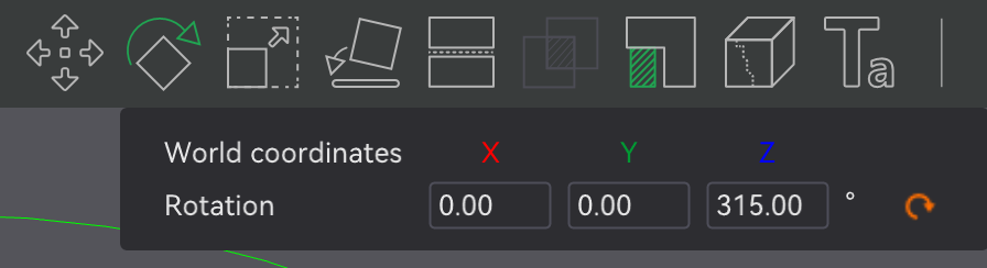
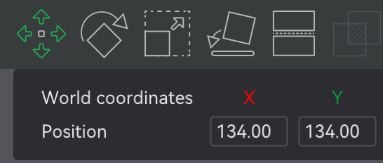
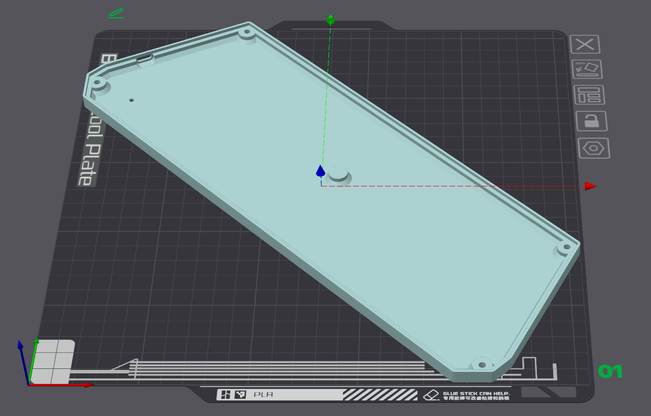
For all the following prints:
-
To fit object in the bed, Z rotate: 315 degree, X, Y move to: 134mm
-
PLA, PETG, ABS are all OK.
-
Layer height: 0.2mm
-
4-6 walls, 50+% infill
-
Support: Yes. If you have Bambu AMS system, use their special support material at interface layers.
-
-
Base:
Production\3D\chu_pico_base.stl, dark gray filament. -
Cover:
Production\3D\chu_pico_cover(_aime).stl, dark gray filament. -
Cover Base:
Production\3D\chu_pico_cover_base.stl, clear transparent (IMPORTANT) filament. -
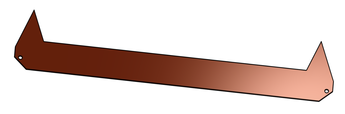
Light Guide Panel Fixer:
Production\3D\chu_pico_lgp_fixer.stl, color doesn't matter.
Exploded View for Assembly
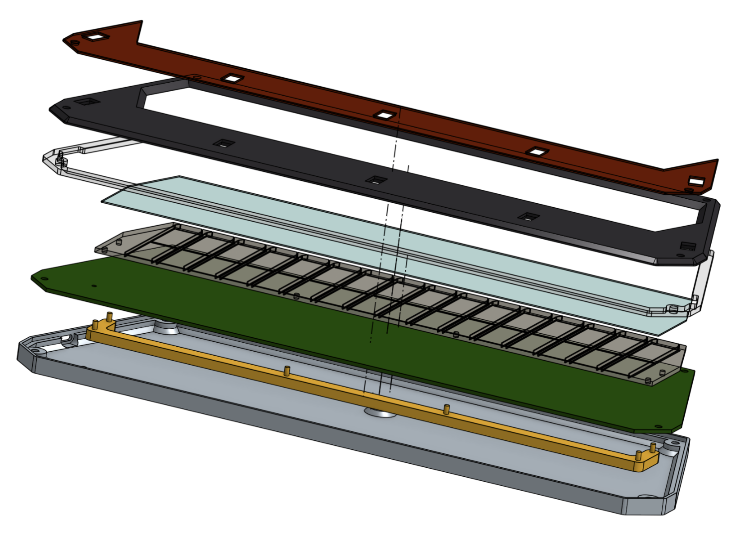
From top to bottom:
- IR Cover
- Cover
- Cover Base
- Panel Film
- Light Guide Panel
- PCB
- Light Guide Panel Fixer
- Base
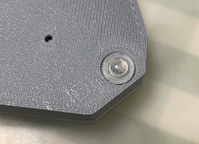
You need 4x M3*12mm screws and 4x M3 hex nuts to fix all things.
7x silicone anti-slip pads can be applied to the bottom side of the base to provide stability when playing.
IR Air Tower
This is not necessary for Chu Pico. But some people may prefer the traditional IR air tower, especially when they're using Chu Pico design for a full-sized controller. So hereby I provide the IR air tower design, with a pair of air tower PCBs and the firmware support.
-
First, you need to order the sensor PCBs, the gerber file is
Production\PCB\chu_air_v*.zip. It's for both sides of the air tower. -
Order the components, they're marked in the schematic. Then solder them to the PCB following the silkscreen.
-
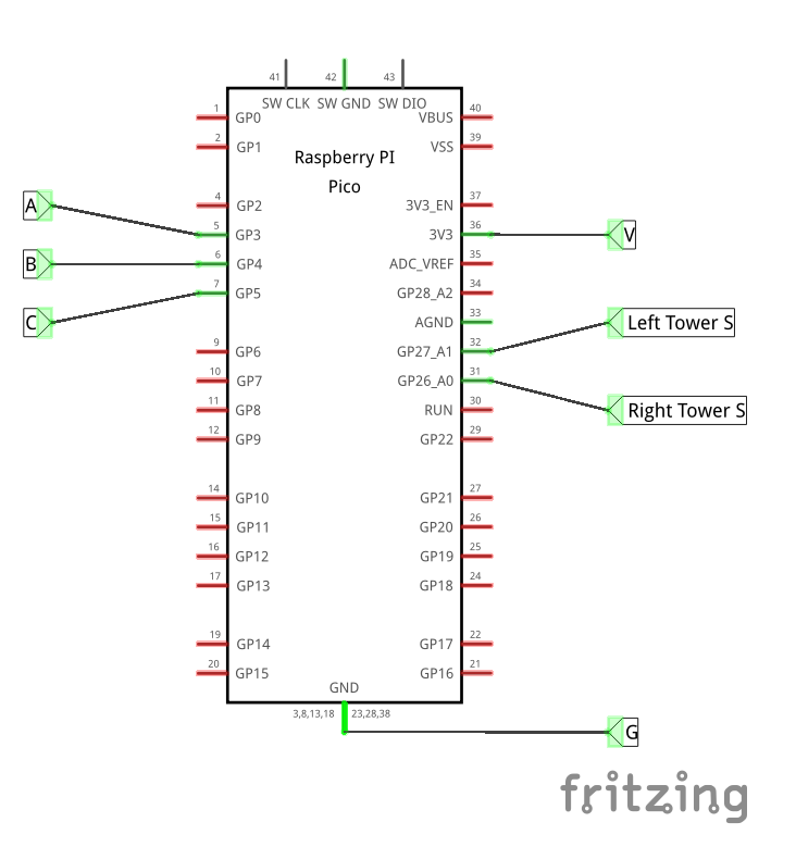
For left side PCB, use J1 to connect to the Raspberry Pi Pico, and for the right side PCB, use J2. GPIO 3 -> A, GPIO 4 -> B, GPIO 5 -> C, ADC 0 (GPIO 26) -> Right S, ADC 1 (GPIO 27) -> Left S.

-
Steps for deployment.
- Enable IR sensor in the firmware (command
ir enable), this will disable ToF. - Enable diagnostics for IR (command
ir diagnostic). - Orientation of the PCB: for the left side PCB, its J1 is at the lowest, for the right side PCB, its J2 is at the lowest (up-side-down).
- Place the air towers and watch the output of the diagnostics, higher value means beam is received.
- Set the baseline after the towers are properly placed (command
ir baseline). - Optionally, set the sensitivity, it's a percentage of expected change (command
ir trigger <1..100>).
- Enable IR sensor in the firmware (command
Firmware
- UF2 file is in
Production\Firmwarefolder. - For the new build, hold the BOOTSEL button while connect the USB to a PC, there will be a disk named "RPI-RP2" showed up. Drag the UF2 firmware binary file into it. That's it. There's a small hole at the bottom side of the Chu Pico, it is facing right to the BOOTSEL button.
- It works on CrazyRedMachine's RedBoard protocol. For more information, please check out CrazyRedMachine's project (Don't forget to give him a star and drop by his GitHub for other cool projects):
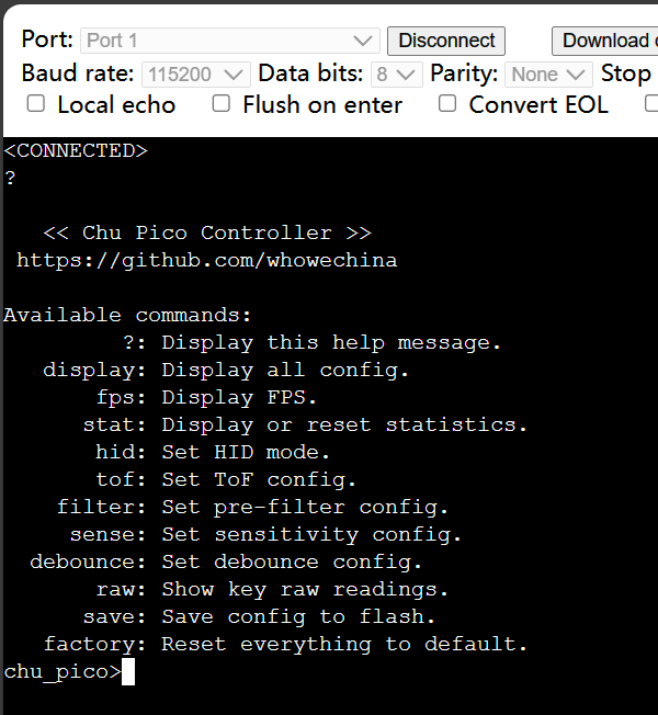
https://github.com/CrazyRedMachine/RedBoard - It has a command line to do configuration. You can use this Web Serial Terminal to connect to the USB serial port of the Chu Pico. (Note: "?" is for help)
https://googlechromelabs.github.io/serial-terminal/
CAD Source File
I'm using OnShape free subscription. It's powerful but it can't archive original designs to local, so I can only share the link here. STL/DXF/DWG files are exported from this online document.
https://cad.onshape.com/documents/8b9d0fe6ff1bfa4da17d33ee/w/5c7c980a282a19e7ba1db795/e/56ee65492584a3f709c23c49?renderMode=1&uiState=64fd606f17393c0e6f9b19a4